|
Multiple
Stage
Coilgun
Construction
|
||||||||||||||||||||
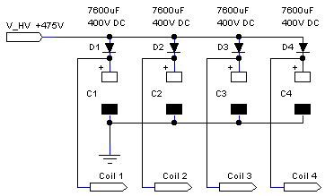
| Capacitor 7600 uF 400 VDC, max surge 475 VDC ½ * C * V² = Joules ½ * 7600exp(-6) * 400² = 608 Joules The
TWR site in
Manhattan Beach Californa sponsors a traditional Swap Meet on the last
Saturday of each month, which
features all matter of sellers ranging from ham radio to computer
products, old and new. My 608 Joules capacitors cost $8 for
singles or $7 each for quantities over 4. Not so much as the swap
meet, but the one gentleman amongst a great number of sellers sells
these caps. Another gentleman sells photocaps by the bucket full for
less than .50 cents each. His motto is, "The bigger the pile, the
bigger the smile." Expanding my stock count beyond my 14 of these
capacitors is ridiculous.
All (-) negative terminals are electrically bolted together by screws and linkers. A linker is made from soldering a ring connecter to each end of 2 parallel strips of 12 AWG solid copper wire. The natural golden-brown color of the copper wire is hidden under a layer of solder. |
||||||||||||||||||||
|
Coil
12 AWG copper wire is wound by hand around a steel rod, which also is the projectile source material. This arrangement achieves very close, 0.5 mm, projectile - coil coupling. A few layers of tape around the rod prevents tight fitting. Generaly, coils undergo a strong contraction force during circuit discharge. However, these coils retain a constant coupling because cyanoacrylate super-bonder adhesive is applied to each layer, raging from 4 to 10. The terminals are terminated with either ring connectors or 12 AWG stranded wire with ring connectors. Meterials: * 12 AWG solid wire * Super-bonder adhesive * Spade connectors * Ring connectors * 12 AWG stranded wire |
||||||||||||||||||||
|
Detector-contact
These simple electrical contacts reduces the component count down to a current limiting resistor. Not only good for a quick test of an SCR switched system, but also they serve good as a quick and simple means of control. Unlike optical detection, the drawback is that the projectile's surface must be conductive, precluding the use of oil lubrication. 3 This detector was designed for mobility. Fitting flush between the rails of the coil mount, the detector may be repositioned at different distances from the coil entrance. A variable position eases the tunning of the capacitor bank pulse widths. Constructed from 3 parts: base, riser,and tube. Base formed from 4 strips of square wooden dowl. Riser formed from 1 strip of dowl and any number of plywood strips for fine tunning if needed, a.k.a. shims. Tube is formed from 1/2 " PVC pipe affixed with music wire and a 2 pin header. Usage: 7-Day CG Cannon 2 This detector was designed for limited space. The spring wire is glued directly onto the exit end of a coil. Usage: ACG 188, ACG 375 1 The housing is a wooden dowel sized to match coil diameter. The four linear gouges excepts two V-shaped metal springs. The metal was procured from mechanical ink pens. This design is better suited for blunt projectiles. Usage: Many multiple stage systems. Materials: * Wooden dowels: round, square * PVC tubing 1/2 " diameter * Music wire 0.015 - 0.025 " diameter * Current limit resistor for SCR gate drive |
||||||||||||||||||||
|
Detector-photo
The housing is a wooden dowel sized to match coil diameter. Two wholes are drilled: one across the diameter to except LEDs, the other through the plane surface to except the projectile. This whole is 25% larger than projectile to allow for a slight mismatch with coil breach. Materials: * Wooden dowel * IR-LED * IR-phototransistor * Bias resistors * Comparator * Vref resistors |
||||||||||||||||||||
| Voltage
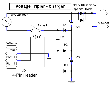
Charger-Tripler Lengthy
charge time is a thing of
the past
thanks be to this AC powered 510VDC generator. In fact, very long
charging times was one of the main reasons I halted my coilgun project
way back in 1997. Now, I have to be carefull when charging capacitors
because even with 2.4KJ the charge time is within 2 seconds. This is
why a charge regulator was designed.
Materials * Capacitors (3) 330V @ 600uF * Diodes (4) 1000V @ 6 A rms, 80 A surge * Relay (1 or 2) 120VAC @ 40 A  |
||||||||||||||||||||
|
Diode
The diodes are placed anti-parallel across each coil. This arrangement protects both the capacitor and the silicon switch from the induced high reverse voltage (back emf) when the coil current has ceased by snubbing the emf down to (-.7v). For my arrangement, 2 diodes in parallel caused 1 to sublimate, and of course the associated Boom sound is included. Actually the sound is more like !!BOOOOMMM!! Materials: * Diodes 1000V @ 6 A rms, 80 A surge * Ring connectors |
||||||||||||||||||||
| Mount-Terminal The
terminal block is the intermediate connection between coils, switches,
diodes, and capacitors. Placed in series, I have 16 strips total
to share for future 6 coils.
Materials:* 8 strip terminal block rated 30A (2) * Fastening scews. |
||||||||||||||||||||
| Mount-Coil Glueing
2 wood dowels to a wood slap makes for straight alignment of multiple
coils. Each coil is fastened down with tightly wrapped masking
tape. Any detetors or sensors are insterted between each coil
stage and may be easily adjusted because the simi-perment masking tape
may be removed/added as needed.
Barrel less Coils So far I have no need for a barrel. Materials: * Wood slab 1/4" x 1 1/2" x 25" * Wood Dowel round or square 3/8" x 25" (2) |
||||||||||||||||||||
|
Mount-Target
The
target mount was made to limit the number of scew hole
manifestations in my table. Now only two screws are used to
fasten this mount to a table. Logically of course, all scew
secured targets are fastened to the mount. The mount's entrance
jig holds layers of sheet metal. Because sheet metal is highly
resilient yet bends fairly easy under high pressure, the aperture of
this jig must be small to prevent the bending of the sheet metal to
where it slips away from its housing. The main housing is just
one long wood slab cut into three even sections of 8".
Materials: * Wood slab 1/2" x 5 1/2" x 24" * Screws * BYOPCSM (bring your own potato, can, and sheet metal) |
||||||||||||||||||||
| Voltage
Charging-Parallel
Though
the capacitors appear as one bank by their close proximity, they are
electrically isolated into 4 individual banks of common ground and
share a common voltage charger. The diode's function is to permit
each capacitor to charge while not being influence by the potential of
another capacitor. The same is true in either idle or discharge
mode. No capacitor leaks into another, no capacitor knows the
existance of another. Simply said, TO EACH ITS OWN.
During charging, the capacitor of least voltage charges first because its respective diode is the first to be biased. Biased diodes are diodes turned on because the potential difference from anode to cathode exceeds a V(threshold) > 0.5v. The non charging banks have the cathode voltage of its respective diodes greater than its anodes; hence the diode is turned off. These banks remain non charging until the voltage of the charging bank rises to equal the next V(threshold) whatever it may be. Simply said, LEAST FULL FILLS FIRST. In the beginning, man was clue less and hasty. The gift of high voltage rendered him giddy and proud. Then the sudden existence of division distorted all elation into perplexity. After a great head scratching, exhaustion from facial expressions, and pile of exfoliation festered from his nail biting, man stud to his feat and said, "Aha I will charge each capacitor one at a time". All was well for a while until man's natural idiosyncrasy of haste spawned visions of less time. Less time to charge, less physical motion needed for charging, the search for such things brought about bafflement. The usual brain storming ensued until charging by relay had came through. This implementation did reduced the number of physical movements inherent to manual wire swapping. However, the problem of time remained. Fed up with the time problem and replacing burned out relays, man decided to reach deep into his mind to find that which is sublime. Materials * Diodes (4) 1000V @ 6 A rms, 80 A surge  |
||||||||||||||||||||
| Voltage
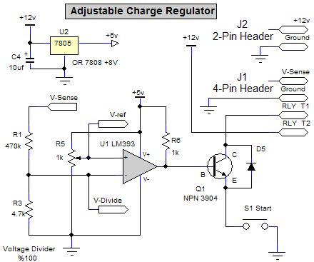
Charging-Regulator The charge regulator
charges a capacitor to
a preset voltage after which the regulator releases power from the AC
controlling relay. This regulator is controlled manually with a
normally opened push button switch so that one may cease charging
before the preset level is reached. The regulator's main function
is to prevent 450VDC max capacitors from charging to 510VDC max off the
AC powered Voltage Tripler.
Materials * Comparator LM339 * 5V regulator LM7805 * NPN transistor 2n3904 * Voltage divider resistors 470K, 4.7k * Potentiometer for reference voltage 1K * Anti parallel protecting diode. * N.O. push button switch  |
||||||||||||||||||||
|
|
| Navigation | ||||||||||||
|
|
|
|
Source Energy
Capacitor: 400v @ 7600 uF, QTY 4Potential : 2,432 Joules Bank 1: 400v + 400v = 800v @ 3600 uF Bank 2: 400v + 400v = 800v @ 3600 uF |
| Projectile
# 1 25 Joules Kinetic Energy Velocity = 43.8 meters/second Weight = 26 grams Length = 7.1 centimeters |
| SCR 800v 40A-rms 520A-surge Brand = Teccor QTY = 6 in parallel for Banks 1, 2 Cost = $2.70 each |
| Coil Hand wound 6 layered 26 turns of 12 AWG wire Equipped with terminal mounts |
| Cyanoacrylate
Adhesive This is a generic bottle used to hold together coils, coil mounts, screw bolts, and SCRs. Basically, this is the liquid form of duct tape. |
| Capacitor 7600 uF 400 VDC, max. surge 475 VDC ½ * C * V² = Joules ½ * 7600exp(-6) * 400² = 608 Joules |
| 1000 V 6 Amperes 4 in parallel Materials: * Diodes * Ring connectors |
| Voltage Tripler Input = 120 vAC (rms) Output = 510 vDC(peek) Materials: * Diodes 1000V 6A (4) * Capacitors 330V 600 uF (3) * Relay |
| The Penetrator Steep pointed angle designed for the purpose of penetrating steel sheet metal and food cans. |
| Coil
#3 Hand wound 4 layered 18 turns of 12 AWG solid copper wire. Equipped with 12 AWG stranded speaker wire and ring connectors. |